- 본 도서의 개정판이 출간되었습니다.
이미 소장하고 있다면 판매해 보세요.
- 국내배송만 가능
- 문화비소득공제 가능
책소개
목차
|
Preface.
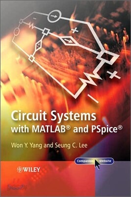
Limits of Liability and Disclaimer of Warranty of Software. 1 Basic Concepts on Electric Circuits. 1.1 Symbols and Units. 1.2 Network Variables. 1.2.1 Voltage and Current. 1.2.2 Electric Power and Energy. 1.2.3 Reference Polarity and Direction of Voltage/Current. 1.2.4 Passive Sign Convention. 1.3 Circuit Elements. 1.3.1 Passive Elements. 1.3.2 Active Elements. 1.3.3 Operational Amplifier. 1.3.4 Transistor. 1.4 Kirchhoff’s Laws. 1.4.1 Nodes, Branches, and Meshes/Loops. 1.4.2 Kirchhoff’s Current Law (KCL). 1.4.3 Kirchhoff’s Voltage Law (KVL). 1.4.4 The Number of KCL/KVL Equations. 1.5 Equivalent Transformation of Sources. 1.5.1 Combination of Several Sources. 1.5.2 Voltage–Current Source Transformation. 1.5.3 Examples of Source Transformation. 1.6 Series and Parallel Connections. Problems. 2 Resistor Circuits. 2.1 Combination of Resistors. 2.1.1 Series Combination of Resistors. 2.1.2 Parallel Combination of Resistors. 2.2 Voltage/Current Divider. 2.2.1 Voltage Divider. 2.2.2 Current Divider. 2.3 Δ-Y(-T) Transformation. 2.3.1 Δ-Y(-T) Conversion Formula. 2.3.2 Y-Δ(T-) Conversion Formula. 2.4 Node Analysis. 2.4.1 Circuits Having No Dependent Sources. 2.4.2 Circuits Having Dependent Sources. 2.5 Mesh (Loop)Analysis. 2.5.1 Circuits Having No Dependent Sources. 2.5.2 Circuits Having Dependent Sources. 2.6 Comparison of Node Analysis and Mesh Analysis. 2.7 Thevenin/Norton Equivalent Circuits. 2.8 Superposition Principle and Linearity. 2.9 OP Amp Circuits with Resistors. 2.9.1 Inverting OP Amp Circuit. 2.9.2 Noninverting OP Amp Circuit. 2.9.3 Voltage Follower. 2.9.4 More Exact Analysis of OP Amp Circuits. 2.9.5 OP Amp Circuits with Positive Feedback. 2.10 Transistor Circuits. 2.11 Loading Effect and Input/Output Resistance. 2.12 Load Line Analysis of Nonlinear Resistor Circuits. 2.13 More Examples of Resistor Circuits. Problems. 3 First-Order Circuits. 3.1 Characteristics of Inductors and Capacitors. 3.1.1 Inductor. 3.1.2 Capacitor. 3.2 Series–Parallel Combination of Inductors/Capacitors. 3.2.1 Series–Parallel Combination of Inductors. 3.2.2 Series–Parallel Combination of Capacitors. 3.3 Circuit Analysis Using the Laplace Transform. 3.3.1 The Laplace Transform for a First-Order Differential Equation. 3.3.2 Transformed Equivalent Circuits for R, L, and C. 3.4 Analysis of First-Order Circuits. 3.4.1 DC-Excited RL Circuits. 3.4.2 DC-Excited RC Circuits. 3.4.3 Time-Constant and Natural Responses of First-Order Circuits. 3.4.4 Sequential Switching. 3.4.5 AC-Excited First-Order Circuits. 3.5 Analysis of First-Order OP Amp Circuits. 3.5.1 First-Order OP Amp Circuits with Negative Feedback. 3.5.2 First-Order OP Amp Circuits with Positive Feedback. 3.6 LRL Circuits and CRC Circuits. 3.6.1 An LRL Circuit. 3.6.2 A CRC Circuit. 3.6.3 Conservation of Flux Linkage and Charge. 3.6.4 A Measure Against Violation of the Continuity Rule on the Inductor Current. 3.7 Simulation Using PSpice and MATLAB. 3.7.1 An RC Circuit with Sequential Switching. 3.7.2 An AC-Excited RL Circuit. 3.8 Application and Design of First-Order Circuits. Problems. 4 Second-Order Circuits. 4.1 The Laplace Transform For Second-Order Differential Equations. 4.1.1 Overdamped Case with Two Distinct Real Characteristic Roots. 4.1.2 Critically Damped Case with Double Real Characteristic Roots. 4.1.3 Underdamped Case with Two Distinct Complex Characteristic Roots. 4.1.4 Stability of a System and Location of its Characteristic Roots. 4.2 Analysis of Second-Order Circuits. 4.2.1 A Series RLC Circuit. 4.2.2 A Parallel RLC Circuit. 4.2.3 Two-Mesh/Node Circuit. 4.2.4 Circuits Having Dependent Sources. 4.2.5 Thevenin Equivalent Circuit. 4.3 Second-Order OP Amp Circuits. 4.4 Analogy and Duality. 4.4.1 Analogy. 4.4.2 Duality. 4.5 Transfer Function, Impulse Response, and Convolution. 4.5.1 Linear Systems. 4.5.2 Time-Invariant Systems. 4.5.3 The Pulse Response of a Linear Time-Invariant System. 4.5.4 The Input–Output Relationship of a Linear Time-Invariant System. 4.6 The Steady-State Response to a Sinusoidal Input. 4.7 An Example of MATLAB Analysis and PSpice Simulation. Problems. 5 Magnetically Coupled Circuits. 5.1 Self-Inductance. 5.2 Mutual Inductance. 5.3 Relative Polarity of Induced Voltages and Dot Convention. 5.3.1 Dot Convention and Sign of Mutual Inductance Terms. 5.3.2 Measurement of the Relative Winding Direction. 5.3.3 Measurement of Mutual Inductance. 5.3.4 Energy in Magnetically Coupled Coils. 5.4 Equivalent Models of Magnetically Coupled Coils. 5.4.1 T-Equivalent Circuit. 5.4.2 -Equivalent Circuit. 5.5 Ideal Transformer. 5.6 Linear Transformer. 5.7 Autotransformers. Problems. 6 AC Circuits. 6.1 Sinusoidal Sources. 6.2 Phasor and AC Analysis. 6.3 AC Impedance of Passive Elements. 6.3.1 Resistor. 6.3.2 Inductor. 6.3.3 Capacitor. 6.4 AC Circuit Examples. 6.5 Instantaneous, Active, Reactive, and Complex Power. 6.6 Power Factor. 6.7 Maximum Power Transfer – Impedance Matching. 6.8 Load Flow Calculation. 6.9 Design and Simulation for Maximum Power Transfer. Problems. 7 Three-Phase AC Circuits. 7.1 Balanced Three-Phase Voltages. 7.2 Power of Balanced Three-Phase Loads. 7.3 Measurement of Three-Phase Power. 7.4 Three-Phase Power System. 7.5 Electric Shock and Grounding. Problems. 8 Frequency Selective Circuit – Filter. 8.1 Lowpass Filter (LPF). 8.1.1 Series LR Circuit. 8.1.2 Series RC Circuit. 8.2 Highpass Filter (HPF). 8.2.1 Series CR Circuit. 8.2.2 Series RL Circuit. 8.3 Bandpass Filter (BPF). 8.3.1 Series RLC Circuit and Series Resonance. 8.3.2 Parallel RLC Circuit and Parallel Resonance. 8.4 Bandstop Filter (BSF). 8.4.1 Series RLC Circuit. 8.4.2 Parallel RLC Circuit. 8.5 Active Filter. 8.5.1 First-Order Active Filter. 8.5.2 Second-Order Active LPF/HPF. 8.5.3 Second-Order Active BPF. 8.5.4 Second-Order Active BSF. 8.6 Analog Filter Design. Problems. 9 Circuits Analysis Using Fourier Series. 9.1 Fourier Series. 9.2 Computation of Fourier Coefficients Using Symmetry. 9.3 Circuit Analysis Using Fourier Series. 9.4 Fourier Series and Laplace Transform. 9.5 RMS Value and Power of a Nonsinusoidal Periodic Signal. 9.5.1 RMS Value and Distortion Factor of a Nonsinusoidal Periodic Signal. 9.5.2 Power and Power Factor of a Nonsinusoidal Periodic Signal. Problems. 10 Two-Port Networks. 10.1 Definitions of Two-Port Parameters. 10.2 Relationships Among Two-Port Parameters. 10.2.1 The z-Parameters and a-Parameters. 10.2.2 The a-Parameters and h-Parameters. 10.2.3 The z-Parameters and h-Parameters. 10.3 Reciprocity of a Two-Port Network. 10.4 Interconnection of Two-Port Networks. 10.4.1 Series Connection and z-Parameters. 10.4.2 Parallel (Shunt) Connection and y-Parameters. 10.4.3 Series–Parallel (Shunt) Connection and h-Parameters. 10.4.4 Parallel (Shunt)–Series Connection and g-Parameters. 10.4.5 Cascade Connection and a-Parameters. 10.4.6 Curse of the Port Condition (Current Requirement). 10.5 Two-Port Networks Having Source/Load. 10.5.1 Input Impedance. 10.5.2 Voltage Gain. 10.5.3 Current Gain. 10.5.4 (Thevenin) Equivalent Impedance Seen from the Output. 10.5.5 (Thevenin) Equivalent Source Seen from the Output. 10.5.6 The Parameters of an Overall Two-Port Network. 10.6 Feedback Amplifiers as Two-Port Networks. 10.6.1 Series–Parallel (Shunt) Feedback Amplifier. 10.6.2 Series–Series Feedback Amplifier. 10.6.3 Parallel–Parallel Feedback Amplifier. 10.6.4 Parallel (Shunt)–Series Feedback Amplifier. 10.6.5 General Feedback Structure. 10.7 Circuit Models with Given Parameters. 10.7.1 Circuit Model with Given z-Parameters. 10.7.2 Circuit Model with Given y-Parameters. 10.7.3 Circuit Model with Given h and g-Parameters. 10.7.4 Circuit Model with Given a and b-Parameters. Problems. Appendices. Appendix A: Laplace Transform. Appendix B: Matrix Operations with MATLAB. Appendix C: Complex Number Operations with MATLAB. Appendix D: Nonlinear/Differential Equations with MATLAB. Appendix E: Symbolic Computations with MATLAB. Appendix F: Useful Formulas (Reference [K-2]). Appendix G: The Standard Values of Resistors, Capacitors, and Inductors. Appendix H: OrCAD/PSpice (References [K-1] and [R-2]). Appendix I: MATLAB Introduction (Reference [K-2]). Appendix J: Solutions to Problems. References. Index. |
품목정보
- 발행일
- 2007년 08월 24일
- 쪽수, 무게, 크기
- 529쪽 | 크기확인중
- ISBN13
- 9780470822326
리뷰/한줄평0
상품정보안내
직수입외서의 경우, 해외거래처에서 제공하는 정보가 부족하여 제목, 표지, 가격, 유통상태 등의 정보가 미비하거나 변경되는 경우가 있습니다. 정확한 확인을 원하시는 경우, 일대일 상담으로 문의하여 주시면 답변 드리겠습니다.
(판형과 판수 등이 다양한 도서는 찾으시는 도서의 ISBN을 알려 주시면 보다 빠르고 정확한 안내가 가능합니다.)
해외거래처에서 품절인 경우, 2차 거래선을 통해 유럽과 미국 출판사로 직접 수입이 진행될 수 있습니다.
수입 진행 시점으로 부터 2~3주가 추가로 소요되며, 해외에서도 유통이 원활하지 않은 도서는 품절 안내가 지연될 수 있습니다.
해당 경우, 문자와 메일로 별도 안내를 드리고 있사오니 마이페이지에서 휴대전화번호와 메일주소를 다시 한번 확인해주시기 바랍니다.
(판형과 판수 등이 다양한 도서는 찾으시는 도서의 ISBN을 알려 주시면 보다 빠르고 정확한 안내가 가능합니다.)
해외거래처에서 품절인 경우, 2차 거래선을 통해 유럽과 미국 출판사로 직접 수입이 진행될 수 있습니다.
수입 진행 시점으로 부터 2~3주가 추가로 소요되며, 해외에서도 유통이 원활하지 않은 도서는 품절 안내가 지연될 수 있습니다.
해당 경우, 문자와 메일로 별도 안내를 드리고 있사오니 마이페이지에서 휴대전화번호와 메일주소를 다시 한번 확인해주시기 바랍니다.