


이미 소장하고 있다면 판매해 보세요.
- 국내배송만 가능
- 해외 거래처 사정에 의하여 품절/지연 가능
- 도서 정보 중 미표기 사항 안내?
- 문화비소득공제 가능
이 분야의 이벤트
![[분야별] 외국도서 한정수량 특가할인](https://image.yes24.com/sysimage/renew/loadSpace.png)
책소개
목차
|
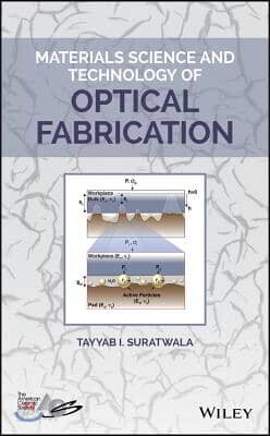
Preface xi Acknowledgments xvii Glossary of Symbols and Abbreviations xix Part I Fundamental Interactions ? Materials Science 1 1 Introduction 3 1.1 Optical-Fabrication Processes 3 1.2 Major Characteristics of the Optical-Fabrication Process 7 1.3 Material Removal Mechanisms 11 References 12 2 Surface Figure 15 2.1 The Preston Equation 15 2.2 The Preston Coefficient 16 2.3 Friction at Interface 19 2.4 Kinematics and Relative Velocity 22 2.5 Pressure Distribution 25 2.5.1 Applied Pressure Distribution 26 2.5.2 Elastic Lap Response 27 2.5.3 Hydrodynamic Forces 28 2.5.4 Moment Forces 31 2.5.5 Viscoelastic and Viscoplastic Lap Properties 34 2.5.5.1 Viscoelastic Lap 34 2.5.5.2 Viscoplastic Lap 38 2.5.6 Workpiece?Lap Mismatch 38 2.5.6.1 Workpiece Shape 41 2.5.6.2 PadWear/Deformation 42 2.5.6.3 Workpiece Bending 44 2.5.6.4 Residual Grinding Stress 47 2.5.6.5 Temperature 51 2.5.6.6 Global Pad Properties 56 2.5.6.7 Slurry Spatial Distribution 58 2.5.6.8 Local Nonlinear Material Deposits 60 2.6 Deterministic Surface Figure 63 References 68 3 Surface Quality 75 3.1 Subsurface Mechanical Damage 75 3.1.1 Indentation Fracture Mechanics 76 3.1.1.1 Static Indentation 76 3.1.1.2 Edge Chipping and Bevels 81 3.1.1.3 Sliding Indentation 84 3.1.1.4 Impact Indentation Fracture 87 3.1.2 SSD During Grinding 92 3.1.2.1 Subsurface Mechanical Depth Distributions 92 3.1.2.2 Relationship of Roughness and Average Crack Length to the Maximum SSD Depth 97 3.1.2.3 Fraction of Abrasive Particles Mechanically Loaded 98 3.1.2.4 Relationship Between the Crack Length and Depth 100 3.1.2.5 SSD Depth-distribution Shape 102 3.1.2.6 Effect of Various Grinding Parameters on SSD Depth Distributions 104 3.1.2.7 Rogue Particles During Grinding 106 3.1.2.8 Conclusions on Grinding SSD 108 3.1.3 SSD During Polishing 109 3.1.4 Effect of Etching on SSD 118 3.1.4.1 Topographical Changes of SSD During Etching 120 3.1.4.2 Influence of SDD Distribution on Etch Rate and Roughness 123 3.1.5 Strategies to Minimize SSD 127 3.2 Debris Particles and Residue 129 3.2.1 Particles 130 3.2.2 Residue 132 3.2.3 Cleaning Strategies and Methods 134 3.3 The Beilby Layer 136 3.3.1 K Penetration by Two-step Diffusion 140 3.3.2 Ce Penetration by Chemical Reactivity 142 3.3.3 Chemical?Structural?Mechanical Model of the Beilby Layer and Polishing Process 145 References 148 4 Surface Roughness 157 4.1 Single-Particle Removal Function 157 4.2 Beilby Layer Properties 166 4.3 Slurry PSD 167 4.4 Pad Mechanical Properties and Topography 170 4.5 Slurry Interface Interactions 174 4.5.1 Slurry Islands and μ-roughness 174 4.5.2 Colloidal Stability of Particles in Slurry 180 4.5.3 Glass Reaction Product Buildup at Polishing Interface 184 4.5.4 Three-Body Forces at Polishing Interface 185 4.6 Slurry Redeposition 187 4.7 Predicting Roughness 192 4.7.1 EHMG ? The Ensemble Hertzian Multi-gap Model 192 4.7.1.1 Pad Deflection and Fraction of Pad Area Making Contact 194 4.7.1.2 Asperity Stress, Interface Gap, Load/Particle Distribution, and Fraction of Active Particles 194 4.7.1.3 Single Particle Removal Function and Load per Particle Distribution 196 4.7.1.4 Monte Carlo Workpiece Roughness Simulation 196 4.7.2 IDG Island-distribution Gap Model 199 4.8 Strategies to Reduce Roughness 204 4.8.1 Strategy 1: Reduce or Narrow the Load-per-particle Distribution 204 4.8.2 Strategy 2: Modify the Removal Function of a Given Slurry 204 References 207 5 Material Removal Rate 211 5.1 Grinding Material Removal Rate 211 5.2 Polishing Material Removal Rate 217 5.2.1 Deviations from Macroscopic Preston Equation 217 5.2.2 Macroscopic Material Removal Trends from Microscopic/Molecular Phenomena 219 5.2.3 Factors Affecting Single-particle Removal Function 226 5.2.3.1 Nanoplastic Effects: Workpiece Hardness 226 5.2.3.2 Chemical Effects: Condensation Rate and Partial-charge Model 228 References 238 Part II Applications ? Materials Technology 241 6 Increasing Yield: Scratch Forensics and Fractography 243 6.1 Fractography 101 243 6.2 Scratch Forensics 248 6.2.1 Scratch Width 249 6.2.2 Scratch Length 251 6.2.3 Scratch Type 251 6.2.4 Scratch Number Density 252 6.2.5 Scratch Orientation and Trailing-indent Curvature 252 6.2.6 Scratch Pattern and Curvature 252 6.2.7 Location on Workpiece 253 6.2.8 Scratch Forensics Example 254 6.3 Slow Crack Growth and Lifetime Predictions 254 6.4 Fracture Case Studies 257 6.4.1 Temperature-induced Fracture 257 6.4.1.1 Laser-Phosphate-glass Thermal Fracture 259 6.4.1.2 KDP Crystal-Workpiece Thermal Fracture 262 6.4.1.3 Thermal Fracture of Multilayers 265 6.4.2 Blunt Loading with Friction 267 6.4.3 Glass-to-metal Contact and Edge Chipping 269 6.4.4 Glue Chipping Fracture 271 6.4.5 Workpiece Failure from Differential Pressure 273 6.4.6 Chemical Interactions and Surface Cracking 276 6.4.6.1 Surface Cracking of Phosphate Glass 276 6.4.6.2 Surface Cracking of the DKDP Crystals 279 References 282 7 Novel Process and Characterization Techniques 285 7.1 Process Techniques 286 7.1.1 Stiff Versus Compliant Blocking 286 7.1.2 Strip Etch and Bulk Etch 290 7.1.3 Pad Wear Management with Septum or Conditioner 291 7.1.4 Hermetically Sealed, High-humidity Polishing Chamber 294 7.1.5 Engineered Filtration System 295 7.1.6 Slurry Chemical Stabilization 296 7.1.7 Slurry Lifetime and Slurry Recycling 300 7.1.8 Ultrasonic Pad Cleaning 301 7.2 Workpiece Characterization Techniques 304 7.2.1 Single-particle Removal Function Using Nanoscratching 304 7.2.2 Subsurface Damage Measurement Using a Taper Wedge 305 7.2.3 Stress Measurement Using the Twyman Effect 306 7.2.4 Beilby Layer Characterization Using SIMS 307 7.2.5 Surface Densification Using Indentation and Annealing 308 7.2.6 Crack Initiation and Growth Constants Using Static Indentation 309 7.3 Polishing- or Grinding-system Characterization Techniques 309 7.3.1 Tail End of Slurry PSD Using SPOS 309 7.3.2 Pad Topography Using Confocal Microscopy 311 7.3.3 Slurry Stability Using Zeta Potential 311 7.3.4 Temperature Distribution During Polishing Using IR Imaging 313 7.3.5 Slurry Spatial Distribution and Viscoelastic Lap Response Using a Nonrotating Workpiece 314 7.3.6 Slurry Reactivity Versus Distance Using Different Pad Grooves 315 References 316 8 Novel Polishing Methods 319 8.1 Magnetorheological Finishing (MRF) 319 8.2 Float Polishing 326 8.3 Ion Beam Figuring (IBF) 329 8.4 Convergent Polishing 331 8.5 Tumble Finishing 336 8.6 Other Subaperture Polishing Methods 344 References 347 9 Laser Damage Resistant Optics 353 9.1 Laser Damage Precursors 356 9.2 Reduction of SSD in Laser Optics 362 9.3 Advanced Mitigation Process 363 References 369 Index 371 ? |
저자 소개
TAYYAB I. SURATWALA, PhD, is Program Director for Optics and Materials Science & Technology (OMST) in the NIF & Photon Science Directorate at Lawrence Livermore National Laboratory. He directs and oversees OMST operations, which include the optics supply for laser programs in the directorate, the NIF optics recycle loop, and the accompanying materials science and technology (including laser damage science & mitigation and optical fabrication).
품목정보
- 발행일
- 2018년 10월 16일
- 쪽수, 무게, 크기
- 416쪽 | 152*231*23mm
- ISBN13
- 9781119423683
리뷰/한줄평0
상품정보안내
직수입외서의 경우, 해외거래처에서 제공하는 정보가 부족하여 제목, 표지, 가격, 유통상태 등의 정보가 미비하거나 변경되는 경우가 있습니다. 정확한 확인을 원하시는 경우, 일대일 상담으로 문의하여 주시면 답변 드리겠습니다.
(판형과 판수 등이 다양한 도서는 찾으시는 도서의 ISBN을 알려 주시면 보다 빠르고 정확한 안내가 가능합니다.)
해외거래처에서 품절인 경우, 2차 거래선을 통해 유럽과 미국 출판사로 직접 수입이 진행될 수 있습니다.
수입 진행 시점으로 부터 2~3주가 추가로 소요되며, 해외에서도 유통이 원활하지 않은 도서는 품절 안내가 지연될 수 있습니다.
해당 경우, 문자와 메일로 별도 안내를 드리고 있사오니 마이페이지에서 휴대전화번호와 메일주소를 다시 한번 확인해주시기 바랍니다.
(판형과 판수 등이 다양한 도서는 찾으시는 도서의 ISBN을 알려 주시면 보다 빠르고 정확한 안내가 가능합니다.)
해외거래처에서 품절인 경우, 2차 거래선을 통해 유럽과 미국 출판사로 직접 수입이 진행될 수 있습니다.
수입 진행 시점으로 부터 2~3주가 추가로 소요되며, 해외에서도 유통이 원활하지 않은 도서는 품절 안내가 지연될 수 있습니다.
해당 경우, 문자와 메일로 별도 안내를 드리고 있사오니 마이페이지에서 휴대전화번호와 메일주소를 다시 한번 확인해주시기 바랍니다.
231,510원
총 1개
231,510원