
이미 소장하고 있다면 판매해 보세요.
- 국내배송만 가능
- 문화비소득공제 가능
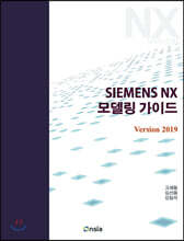
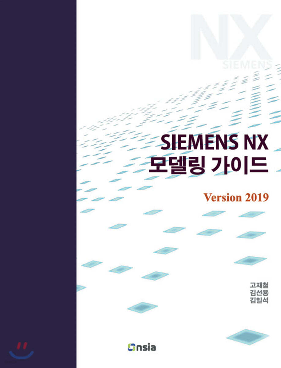
책소개
목차
|
Chapter 1 시작하기
1.1 NX 소개 1.2 NX 시작하기 1.3 새 파트 생성하기 1.4 NX UI(User Interface, 사용자 인터페이스) 1.5 Roles 1.6 마우스 사용법 1.7 스케치와 모델 생성 1.7.1 스케치 생성 1.7.2 사각형 그리기 1.7.3 돌출 시키기 1.8 View 팝업 메뉴 1.9 형상 변경 하기 1.10 형상 추가하기 1.11 형상 제거하기 1.12 파일 관리 1.13 Customer Defaults 1.13.1 Fit Percentage 1.13.2 Continuous Auto Dimensioning in Design Applications 1.13.3 변경 사항 확인 및 삭제 1.14 User Interface 설정 1.14.1 단위창 위치 초기화 1.14.2 정보 메시지 초기화 Chapter 2 스케치와 돌출 기본 2.1 스케치(Sketch)의 정의 2.2 스케치 순서 2.2.1 스케치 면 정의 2.2.2 커브 생성 2.2.3 구속 2.2.4 스케치 종료 2.3 커브 생성 2.3.1 직선(Line) 2.3.2 직선의 구성 요소 2.3.3 원(Circle) 2.3.4 호(Arc) 2.4 Snap Point 옵션 Exercise 01 2.5 선의 드래그 Exercise 02 2.6 스케치 커브의 구속(Constraint) 2.6.1 치수 구속 (Dimensional Constraint) 2.6.2 기하 구속(Geometric Constraint) 2.6.3 대칭 구속 (Make Symmetric) 2.7 스케치 커브의 구속 상태 2.8 구속 상태 확인 2.8.1 Status Line에서 확인하기 2.8.2 선의 색깔로 확인하기 2.8.3 자유도 화살표 2.8.4 드래그 하여 확인하기 2.8.5 각 방법의 특정 2.9 Open in Sketch Task Environment Exercise 03 2.10 스케치 개체 삭제 및 치수 수정 2.10.1 스케치 치수 수정 Exercise 04 2.10.2 Sketch 개체 삭제 Exercise 05 Exercise 06 2.11 기타 스케치 기능 2.11.1 Quick Trim 2.11.2 Fillet 2.11.3 Mirror Curve Exercise 07 2.12 완전 구속의 올바른 이해 2.12.1 잘못된 완전구속의 예 1 2.12.2 잘못된 완전구속의 예 2 2.12.3 완전구속 가이드라인 Exercise 08 Exercise 09 2.13 돌출 2.13.1 와이어프레임(Wireframe) 2.13.2 시트 바디(Sheet Body) 2.13.3 솔리드 바디(Solid Body) 2.13.4 폐곡선 안의 다른 폐곡선 2.13.5 섹션(Section) 2.13.6 교차하는 섹션 Exercise 10 Exercise 11 Exercise 12 2.14 참조치수와 참조선 Exercise 13 2.15 자동 치수의 이해 Exercise 14 Exercise 15 Exercise 16 Exercise 17 Chapter 3 3차원 형상 생성 기능 3.1 Extrude 기능 3.1.1 Section 3.1.2 Direction 3.1.3 Limits 3.1.4 Boolean 3.1.5 Draft 3.1.6 Offset 3.2 섹션 (Section) 3.2.1 Curve Rule 3.1.7 Stop at Intersection(그림 3-7의 ) 3.2.2 Follow Fillet(그림 3-7의 ) 3.2.3 Chain within Feature(그림 3-7의 ) Exercise 01 3.3 Hide와 Show 3.4 Boolean 옵션 3.4.1 Unite 3.4.2 Subtract 3.4.3 Intersect 3.4.4 None 3.4.5 바디간의 불리언 작업 Exercise 02 3.5 스케치 좌표계 3.6 Limit 옵션 3.6.1 Symmetric Value 3.6.2 Until Next 3.6.3 Until Selected 3.6.4 Until Extended 3.6.5 Through All 3.7 Extrude의 다른 옵션 3.7.1 Draft 3.7.2 Offset 3.7.3 Open Profile Smart Volume Exercise 03 Exercise 04 Exercise 05 3.8 오브젝트의 색상 바꾸기 3.9 회전 형상 만들기(Revolve) 3.9.1 Revolve의 섹션과 축 3.10 구멍 뚫기 3.10.1 General Type Hole 3.10.2 Threaded Type Hole Exercise 06 3.11 Design Feature 3.11.1 Block 3.11.2 Cylinder 3.11.3 Cone 3.11.4 Sphere Exercise 07 Exercise 08 Exercise 09 Exercise 10 Exercise 11 Exercise 12 Exercise 13 Exercise 14 Chapter 4 데이텀 (Datum) 4.1 데이텀이란? 4.2 데이텀 평면(Datum Plane) Exercise 01 Exercise 02 Exercise 03 4.3 점 (Point) 4.3.1 Output Coordinates 4.3.2 Offset 4.3.3 Associative 옵션 Exercise 04 Exercise 05 4.4 데이텀 축(Datum Axis) Exercise 06 4.5 데이텀 좌표계 Exercise 07 Exercise 08 Exercise 09 Exercise 10 Exercise 11 Exercise 12 Exercise 13 Chapter 5 추가 모델링 기능 I 5.1 상세 모델링 5.2 Edge Blend 5.2.1 Edge Blend의 종류 Exercise 01 5.2.2 Continuity 옵션 5.2.3 Shape 옵션 Exercise 02 5.2.4 블렌드 생성 가이드 라인 Exercise 03 Exercise 04 Exercise 05 Exercise 06 Exercise 07 5.3 Face Blend 5.3.1 Two Face 5.3.2 Three Face Exercise 08 5.4 Chamfer 5.4.1 기능 사용 절차 5.4.2 Cross Section 옵션 5.4.3 Offset Method 5.5 Draft 5.5.1 Draft Type Exercise 09 Exercise 10 Exercise 11 Exercise 12 5.5.2 Draft의 기타 옵션 5.6 Shell 5.6.1 Reverse Direction 5.6.2 Alternate Thickness 옵션 Exercise 13 Exercise 14 Exercise 15 Exercise 16 Exercise 17 Exercise 18 Chapter 6 모델 수정 6.1 모델 수정의 이해 6.1.1 피쳐의 Parents - Children 관계 6.1.2 피쳐의 삭제 6.2 Sketch 수정 Exercise 01 6.2.1 스케치 면 변경 6.3 Feature 삽입 (Make Current Feature) Exercise 02 6.4 Feature Definition 수정 6.4.1 선택한 개체 변경 Exercise 03 Exercise 04 6.5 Feature의 순서 변경 (Reorder) Exercise 05 Exercise 06 Exercise 07 Exercise 08 Chapter 7 피쳐 및 오브젝트의 복사 7.1 피쳐, 오브젝트를 복사하는 방법의 장점 7.2 복사의 대상과 방법 7.2.1 복사의 대상 7.2.2 복사 방법 7.3 Pattern Feature 7.3.1 Linear 타입 Exercise 01 Exercise 02 7.3.2 Pattern Feature 기능 사용시 주의 사항 Exercise 03 7.3.3 Circular 타입 Exercise 04 Exercise 05 7.3.4 General 타입 7.4 Mirror Feature 7.5 지오메트리의 복사 7.5.1 Mirror Geometry 7.5.2 Pattern Geometry Exercise 06 7.6 Face의 복사 Exercise 07 7.7 피쳐의 복사/붙여넣기 Exercise 08 Exercise 09 Exercise 10 Exercise 11 Exercise 12 Chapter 8 추가 모델링 기능 II 8.1 Trim Body 8.1.1 기능 사용 절차 Exercise 01 Exercise 02 8.2 Tube 8.3 Sweep along Guide 8.3.1 기능 사용 절차 Exercise 03 8.4 Swept Exercise 04 Exercise 05 8.5 Emboss 8.6 Synchronous Modeling 8.6.1 Move Face Exercise 06 8.6.2 Resize Blend 8.6.3 Delete Face Exercise 07 8.6.4 Copy Face 8.6.5 Make Coplanar 8.6.6 Linear Dimension Exercise 08 Exercise 09 8.6.7 Radial Dimension Exercise 10 Exercise 11 Exercise 12 Chapter 9 고급 스케치와 측정 기능 9.1 Intersection Point 9.2 Intersection Curve Exercise 01 9.3 Project Curve Exercise 02 9.4 Offset Curve Exercise 03 9.5 Measure 9.5.1 Ojbect to Measure 9.5.2 Result Filter 9.5.3 Measurement Method 9.5.4 Object Set 9.5.5 각도 측정 9.5.6 Settings 옵션 Exercise 04 Exercise 05 Chapter 10 어셈블리 I (Bottom-Up Assembly) 10.1 어셈블리의 이해 10.2 용어 10.2.1 컴포넌트(Component) 10.2.2 마스터 파트(Master Part) 10.2.3 서브 어셈블리(Sub-assembly) 10.2.4 BOM(Bill of Material) 10.2.5 Bottom-Up 어셈블리 모델링 10.2.6 Top-Down 어셈블리 모델링 10.3 어셈블리 모델링의 주요 기능 10.4 어셈블리 생성 10.4.1 어셈블리 파일 생성 Exercise 01 10.4.2 어셈블리 환경 Exercise 02 10.4.3 컴포넌트 추가 10.4.4 어셈블리 파일의 저장 10.4.5 파일 닫기 10.4.6 파일 열기 Exercise 03 10.4.7 Assembly Navigator의 이용 10.4.8 컴포넌트의 이동과 회전 Exercise 04 Exercise 05 10.4.9 컴포넌트의 복사 10.5 어셈블리의 구속 10.5.1 Fix 구속 10.5.2 Touch Align 구속 10.5.3 바람직한 구속 Exercise 06 Exercise 07 10.5.4 컴포넌트 추가하면서 구속 적용하기 10.5.5 Center 구속 Exercise 08 10.5.6 Concentric 구속 10.5.7 기타 구속 10.5.8 구속의 상태 확인 10.5.9 Show and Hide Constraints 10.5.10 구속조건 억제시키기 10.6 Reference Set Exercise 09 Exercise 10 Exercise 11 Chapter 11 어셈블리 II (Top-Down Assembly) 11.1 Context Control 11.1.1 컴포넌트 닫기 11.1.2 컴포넌트 열기 11.1.3 Make Work Part (작업파트로 만들기) 11.1.4 Open in Window Exercise 01 11.2 간섭 체크 11.2.1 간섭의 타입 Exercise 02 11.3 다른 컴포넌트의 형상을 이용한 모델링 11.3.1 Interpart Link 11.3.2 Selection Scope Exercise 03 Exercise 04 11.4 새로운 컴포넌트 생성하기 (새로운 파트와 서브 어셈블리) Exercise 05 Exercise 06 11.5 어셈블리의 분해 Exercise 07 11.6 기타 어셈블리 기능 11.6.1 어셈블리의 화면 표시 11.6.2 단면 표시 Exercise 08 11.6.3 어셈블리의 질량 측정 Exercise 09 Exercise 10 Chapter 12 도면생성 (Part I) 12.1 개요 12.2 주요 용어 12.2.1 도면뷰(Drawing View) 12.2.2 표제란(Title Block) 12.2.3 도면 시트(Drawing Sheet) 12.3 도면 파일 12.3.1 도면 파일 생성하기 12.3.2 도면 화면의 이해 12.3.3 도면 파일 저장 12.4 도면 시트 12.4.1 도면 시트 생성 12.4.2 도면 시트 설정 12.5 도면 뷰(Drawing View) 12.5.1 기본뷰 (Base View) 12.5.2 투영도 (Projected View) Exercise 01 12.5.3 뷰의 스타일 설정 12.5.4 단면도 (Section View) Exercise 02 12.5.5 상세도 (Detail View) Exercise 03 12.5.6 부분 단면도(Break-out Section View) Exercise 04 12.5.7 절단뷰(Break View) 12.6 View Dependent Edit 12.7 View Boundary 변경 Exercise 05 12.8 모델의 형상과 방향 수정 Chapter 13 도면생성 (Part II) 13.1 도면 생성 절차 13.2 치수(Dimension) 기입 13.2.1 치수 팝업 메뉴 13.2.2 치수 보조선 팝업 메뉴 13.2.3 치수선 팝업 메뉴 13.2.4 Linear Dimension 13.2.5 Radial Dimension 13.2.6 Angular Dimension 13.2.7 옵션의 종류 13.2.8 설정의 상속 13.3 치수를 생성한 후의 설정 변경 13.3.1 Dimension 대화상자 13.3.2 팝업툴바 13.3.3 팝업메뉴 13.4 Drafting Preferences 13.5 치수의 정렬 Exercise 01 Exercise 02 13.6 주석(Note) 기입 13.6.1 Note 수정 13.6.2 다중 지시 Note 13.7 중심선 13.7.1 Center Mark 13.7.2 Bolt Circle Centerline 13.7.3 2D Centerline 13.7.4 3D Centerline 13.7.5 Offset Center Point Symbol 13.8 교차기호(Intersection Symbol) Exercise 03 Exercise 04 Exercise 05 13.9 어셈블리 도면 13.9.1 도면 뷰에서 특정 컴포넌트 제외 시키기 Exercise 06 13.9.2 어셈블리의 부분단면도 Exercise 07 13.9.3 분해도 Exercise 08 Appendix A 개체의 선택 A.1 대화상자의 선택 단계 A.2 선택한 개체의 수 A.3 Type Filter A.4 점, 선, 면의 선택 A.4.1 Snap Point 옵션 A.4.2 Curve Rule A.4.3 Face Rule A.5 선택의 취소 A.5.1 모두 선택 취소할 때 A.5.2 일부만 선택 취소할 때 A.6 상세 필터링 A.7 선택 범주 A.8 선택의 우선 순위 A.9 QuickPick |
저자 소개 3
PLM(CAD/CAM/CAE) 분야의 교육, 컨설팅 및 출판을 중심으로 하는 (주)온솔루션인티그레이션의 대표이사이다. 개별 소프트웨어는 상호 유기적으로 연결되고, 고객의 필요에 맞게 새로운 기능들이 추가되어 효과적인 통합을 하는것이 PLM 분야의 나아가야 할 방향이라고 생각하는 그는 온/오프라인 교육과 출판을 중심으로 사람들을 만나고 있다.
고재철의 다른 상품
-
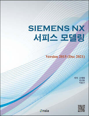
Siemens NX 서피스 모델링 Version 2015 (Dec 2021) 이동Siemens NX 서피스 모델링 Version 2015 (Dec 2021)27,000원 10%

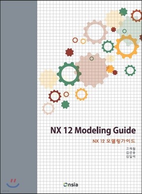
『NX 12 모델링 가이드』의 저자이다.
김선용의 다른 상품
-
Siemens NX 서피스 모델링 Version 2015 (Dec 2021) 이동Siemens NX 서피스 모델링 Version 2015 (Dec 2021)27,000원 10%
『NX 12 모델링 가이드』의 저자이다.
김일석의 다른 상품
관련 분류
- 카테고리 분류
품목정보
사락 별점0
혜택 및 유의사항밑줄0
혜택 및 유의사항
27,000원
총 1개
27,000원